Realtime
Week 1
1. The brief
The Great Outdoors
create an interactive environment or project that will provide a
memorable experience for your users. This could take the form of a physical installation or screen based or even a mixture of the 2. The key component is facilitating rich Realtime Interaction that goes beyond the basics of clicking buttons and aiming a crosshair.
2. What is realtime?
“the actual time during which a process or event occurs.”
In terms of computing:
“relating to a system in which input data is processed within milliseconds so that it is available virtually immediately as feedback to the process from which it is coming, e.g. in a missile guidance system.”
3. Examples
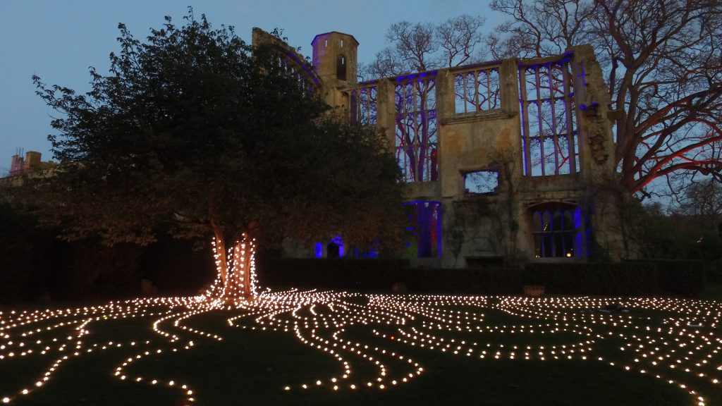
Flow by Squid Soup
‘”Flow’ is a series of explorations using dynamically controlled points of light within physical space to visualise the flow of energy”
https://www.squidsoup.org/portfolio/flow/
Flow is a beautiful installation which integrates technology and nature. The way the light represents the flow of energy is really effective and provides an insight which really connects you to the nature around us .
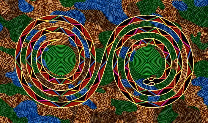
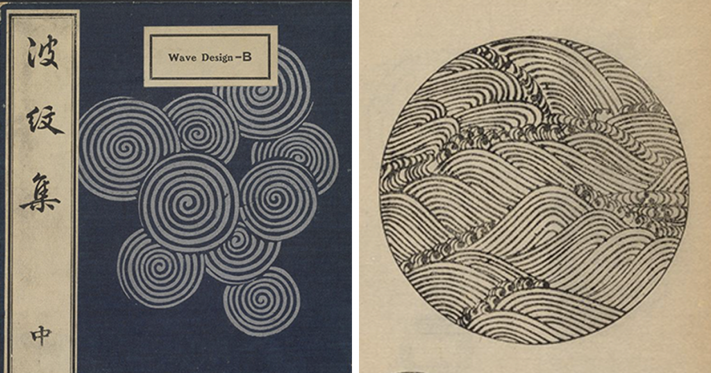
This inspiration for this project comes from both aboriginal dreamtime paintings and Japanese wave designs which is clear to see when compared to the outcome. Both these pieces of art work demonstrate a strong sense of movement within a static design. This is really captured in ‘Flow’ with the considered positioning of the lights which almost mirror the roots reaching out from the tree and all the energy and nutrients travelling through them.
I feel this installation has a message to reconnect with nature and it’s inspiring that we can use technology to promote this idea.
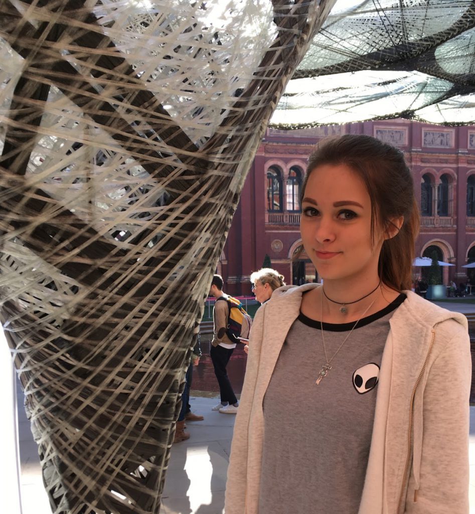
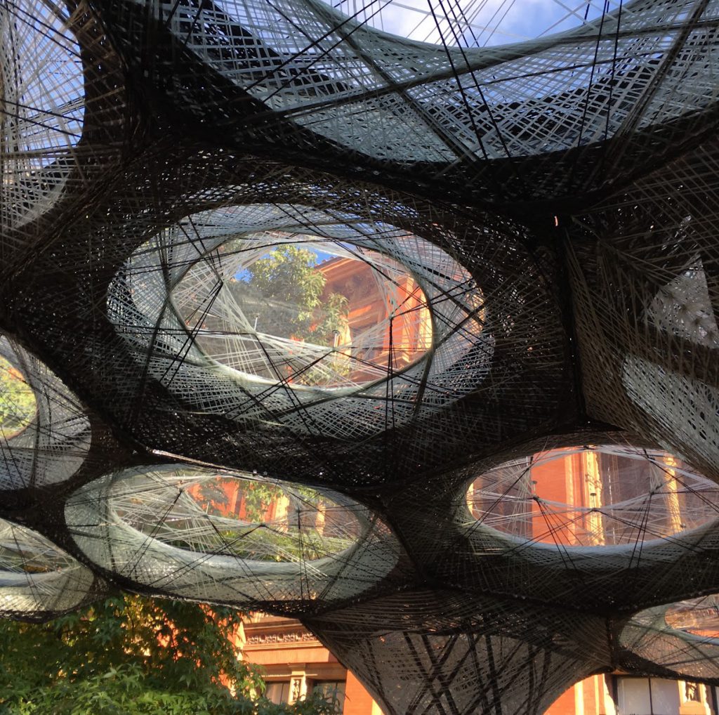
The Elytra Filament Pavilion
“Elytra Filament Pavilion was created by experimental German architect Achim Menges with Moritz Dörstelmann, structural engineer Jan Knippers and climate engineer Thomas Auer.”
I saw this Exhibition in 2016 when it was displayed at the V&A museum in London.
The Pavilion integrates robotic function and new materials found in nature to experiment the impact of emerging robotic technologies on architectural design, engineering and making.
“Its design is inspired by lightweight construction principles found in nature, the filament structures of the forewing shells of flying beetles known as elytra. Made of glass and carbon fibre, each component of the undulating canopy is produced using an innovative robotic winding technique developed by the designers. Like beetle elytra, the pavilion’s filament structure is both very strong and very light – spanning over 200m2 it weighs less than 2,5 tonnes.”
The Pavilion is a responsive shelter that was designed to grow over the course of its exhibition at the V&A museum. There are Sensors in the canopy fibres which collect data on where the visitors interact with the Pavilion. This then informs the canopy on where to ‘grow’. During a series of special events as part of the Engineering Season, visitors had the opportunity to witness the pavilion’s construction live, as new components were fabricated on-site by a Kuka robot.
Week 2
1. Making Interactions
What is Interaction?
“communication or direct involvement with someone or something”
Lesson task –
2 Positive Interactions:
- Using my laptop – it just works, unlike my old one, good storage, good battery, fast etc
- Using the Tube – so quick and easy to get places, efficient and practical and fairly reliable
2 Negative Interaction:
- Using the DLE – can be really hard to find things, especially the right timetable, why are there 3 different ones? Too many routes to the same thing.
- Using my one of the hobs – it doesn’t get very hot so barely boils water even once its full heated up (so I used the other one)
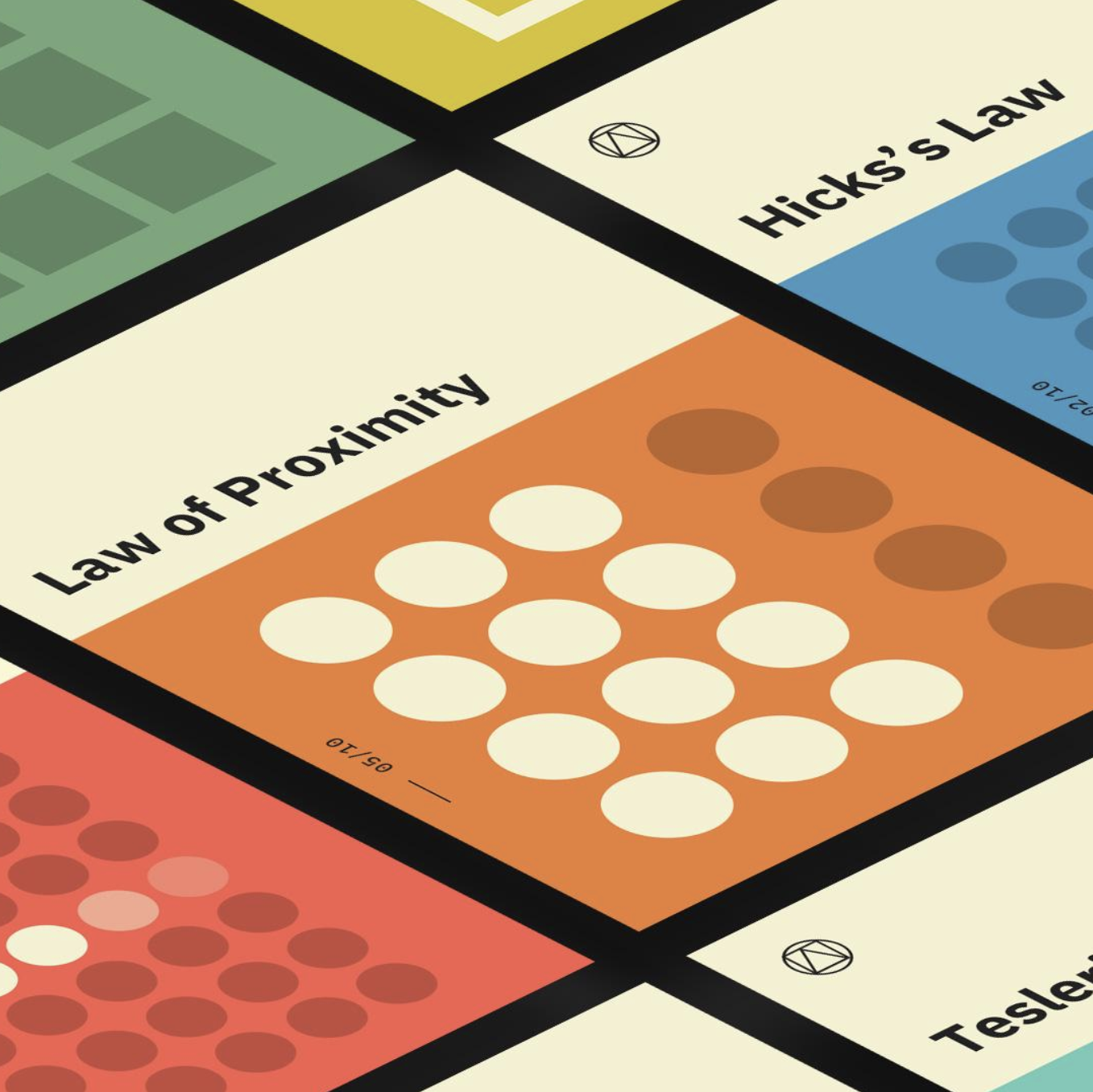
2. UX Laws
- Aesthetic Usability Effect: Users often perceive aesthetically pleasing design as design that’s more usable.
- Doherty Threshold: Productivity soars when a computer and its users interact at a pace (<400ms) that ensures that neither has to wait on the other.
- Jakob’s Law: Users spend most of their time on other sites. This means that users prefer your site to work the same way as all the other sites they already know.
- Miller’s Law: The average person can only keep 7 (plus or minus 2) items in their working memory.
- Hick’s Law: The time it takes to make a decision increases with the number and complexity of choices.
These laws are what matter when creating seamless UX design, and should be considered when creating a piece of work that requires human interaction.
3. Ideation
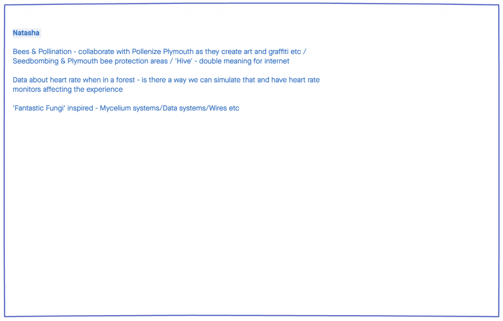
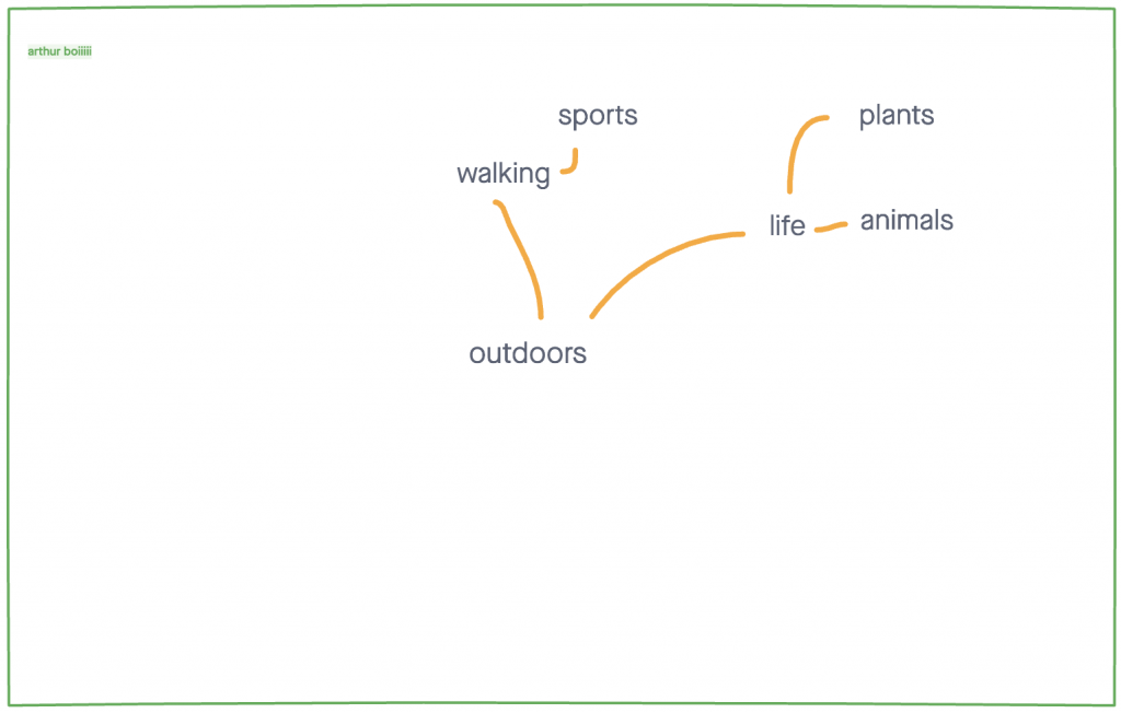
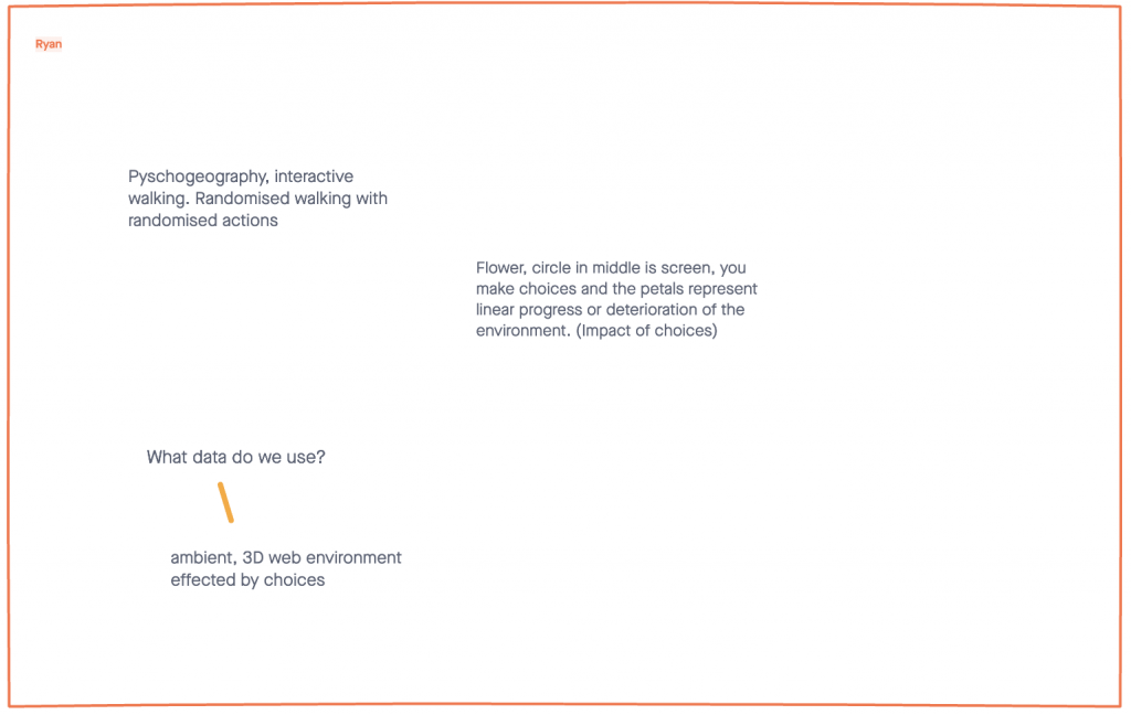
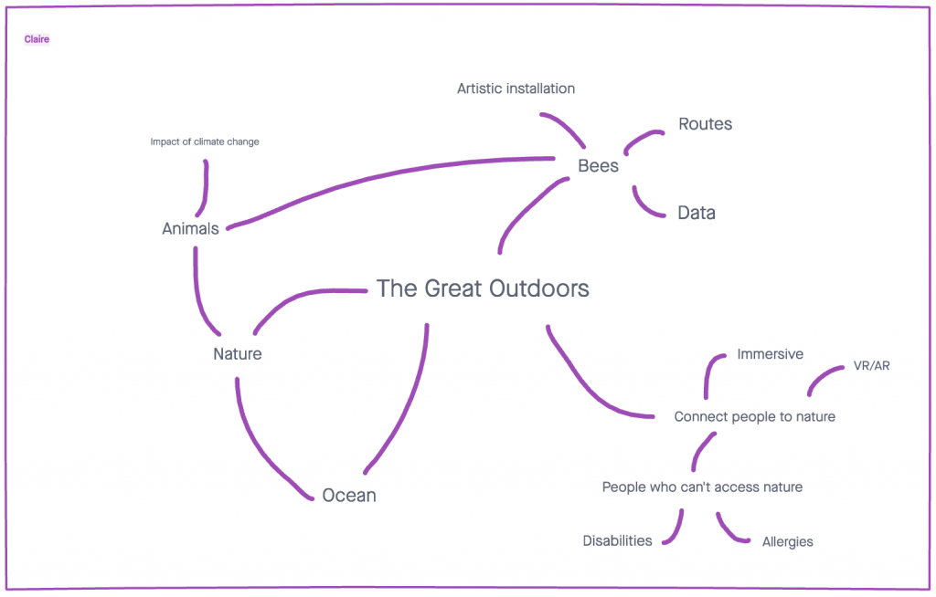
To begin our ideation process we decided to all brainstorm our initial individual ideas.
We all generally had quite aligned ideas. Most of us mentioned nature and trying to create a sense of connection to the outside world.
A couple of us mentioned bees or pollination. We could create an immersive experience in order to educate people on the importance of bee’s role in nature.
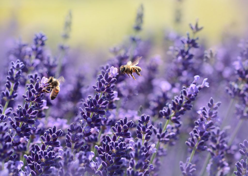
We considered what type of data we could use and where we would source it. Pollenize Plymouth is a company dedicated to saving the bee’s which could be an interesting and beneficial source to get in contact with.
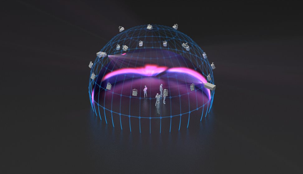
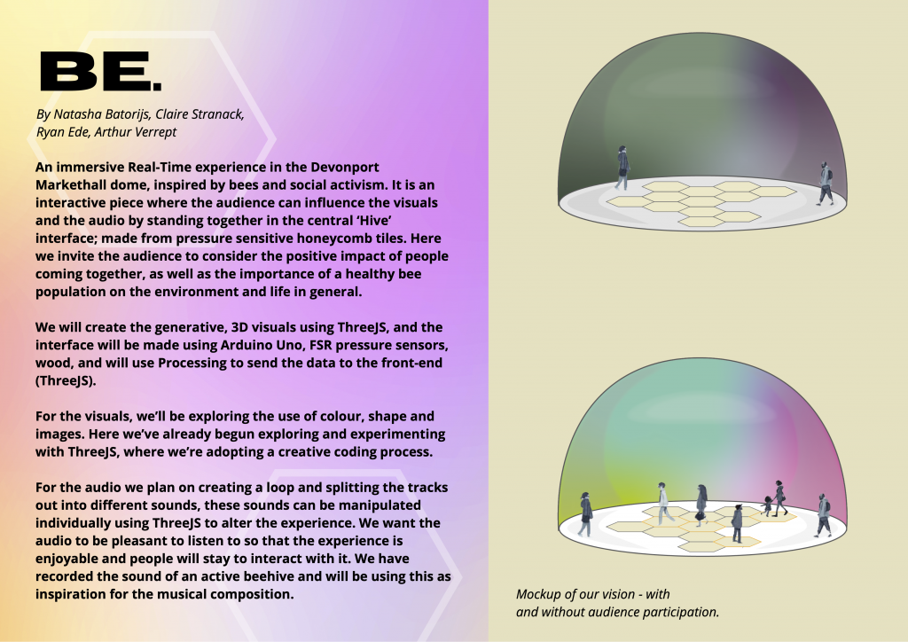
We also considered what form our installation could take, we mentioned the idea of immersion or the creation of an environment. This could be achieved through the use of VR or potentially the dome based in the Market Hall, which could include a lot more people than a single VR headset. We liked the idea of the installation being an experience that can be shared by a large group of people at once.
2. Bee installation
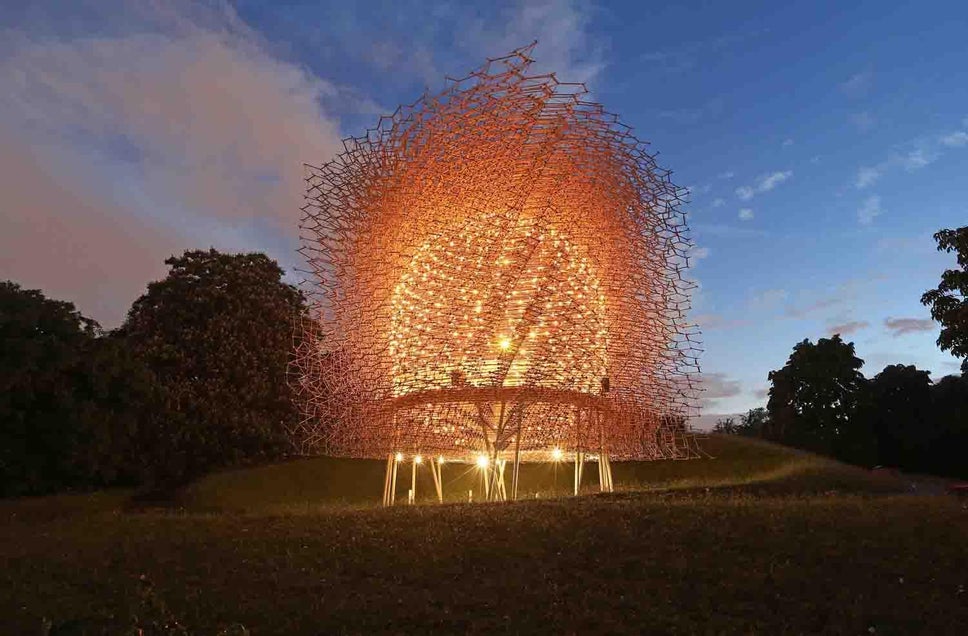
Immersive sound provides the listener with a natural three-dimension At a towering 17 metres tall, The Hive is a striking installation in the heart of a wildflower meadow that recreates life inside a beehive.
Kew Gardens
In 2017, at Kew Gardens, there is an incredible installation by Wolfgang Buttress, called the Hive. It is a structure made of an aluminium lattice, that is controlled by the vibrations of a beehive. The Hive becomes a visual representation of the bee colony’s activity. LED lights and audio are both affected by the bees. The project is meant to create an immersive and peaceful environment where participants can go and experience a real life beehive through artistic representation.
This project is incredibly relevant to what we wanted to create, a real element of immersion, surrounded by bees and nature.
Week 3
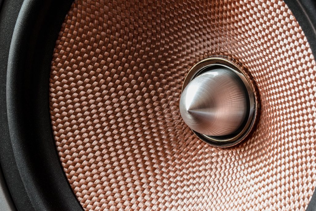
1. Immersive sound
Immersive sound provides the listener with a natural three-dimension sound experience.
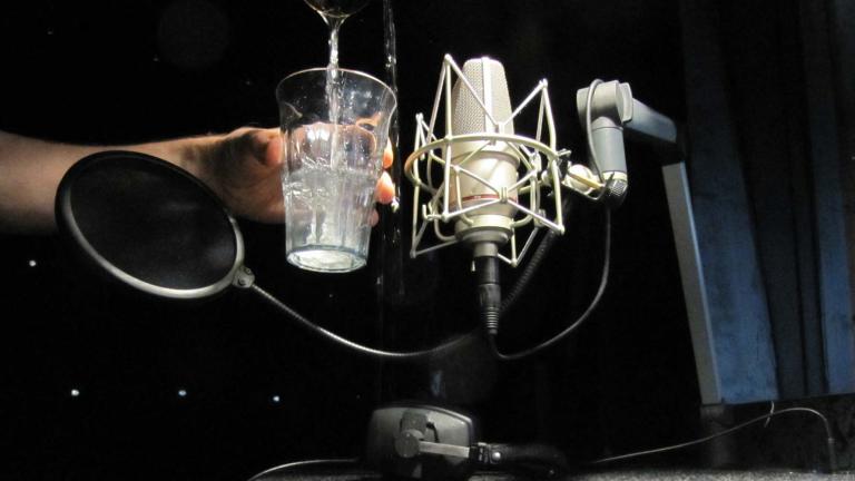
2. Immersive sound Example
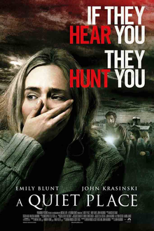
The use of foley in films
What is Foley?
“relating to or concerned with the addition of recorded sound effects after the shooting of a film.”
Jack Foley introduced the idea of foley art used in a variety of films and programs today. Foley art originated from the live broadcast era of the 1920s. Radio studios would hire sound artists to create the effects live on cue and improvise with the radio host during broadcasts. One of the pioneers and most recognised names in the broadcast world was Jack Foley. Jack Foley was the first sound artist to break into the film industry, and create the techniques that foley artists still use to this day.
One of the most interesting films that uses Foley art is ‘The Quiet Place’ by John Krasinski (Academy Award nominated for Sound Editing, 2019). Unlike most other films, this film included foley sounds written into the script. The whole premise of the film centers around the lack of sound with very little speech, which makes the sound effects particularly critical in the overall production. E2 Sound were the foley team for this film and they have worked on multiple famous films and series such as Godzilla, Love and Monsters, Pet Cemetery and many more which can be seen here.
We would like to implement some sound into our project to enhance the environment. As we are interested in basing our project around bee’s we felt that having some recordings of bees would be appropriate, however the noise of a beehive is not always associated with pleasant sounds so we discussed merging it with musical chords to soften the harshness.
3. Research
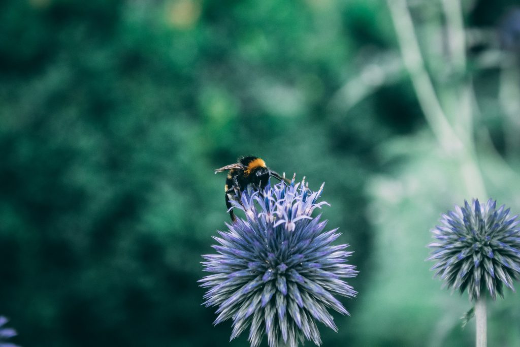
To back up our concept we did a bit of research into the life of Bees, and why an installation like ours is important.
We found the 3 main challenges facing bees are:
- Pesticides – Pesticides can cause considerable harm to bees and other species, blocking neural pathways in their central nervous systems, causing disorientation, inability to feed and death.
- The Varroa Mite – The Varroa Mite attaches itself to the honey bee and sucks its blood. They are unfortunately very successful and once the varroa mite has entered a colony, it can kill the whole colony in 2-3 years. They have been found to be one of the main causes of colony collapse disorder in North America.
- Habitat Loss – An estimated 97% of wildflower meadows disappeared from England and Wales between the 1930s and 1980s; this has contributed to a profound impact on our wildlife, including bees.
Source: Why are bees in danger?
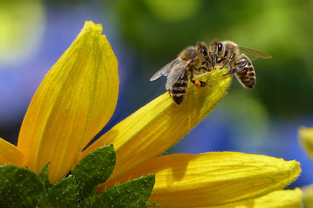
Why are bees so important?
Bees are pollinators, pollinators are vital for life on earth as we know it, without them, we wouldn’t have potatoes, strawberries, tomatoes, coffee, chocolate or cotton! Bees are also part of the insect population worth about £690 million to UK crops each year. 76% of globally important commercial crops depend on insect pollination, which equates to 1 in 3 mouthfuls of food!
It’s clear bees play an incredibly important role in the environment therefore it would be so valuable for our installation to raise awareness and educate people on their crucial role.
Source: Facts about bees
Week 4
1. Immersive Visuals
Vision is an incredibly powerful and valued sense in our modern world. In order to make a truly immersive piece we will have to consider the use of light and shadow, whether we are trying to create realism in terms of visual or lean into something more abstract. All the fine details will impact the overall experience.
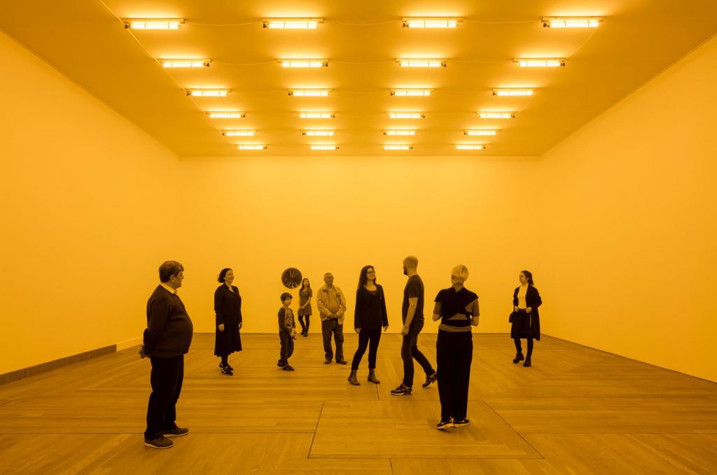
In Room for one colour, by Olafur Eliasson, yellow mono-frequency lamps are mounted to the ceiling of a white room and the yellow light they emit reduces the viewers’ spectral range to yellow and black, all other light frequencies are suppressed. This colour trick creates a neurological response that intensifies the participants’ perception of detail and dimension. Even after leaving the space, there’s a reaction to the yellow environment and viewers are left with an afterimage where their eyes adjust to the broader spectrum of colours.
2. Technologies
We looked at a variety of different technologies we could use to create the interaction between audience and installation. This piece of technology shows how proximity sensors can trigger lights, to turn up their intensity. This could create a really interesting realtime user interaction.
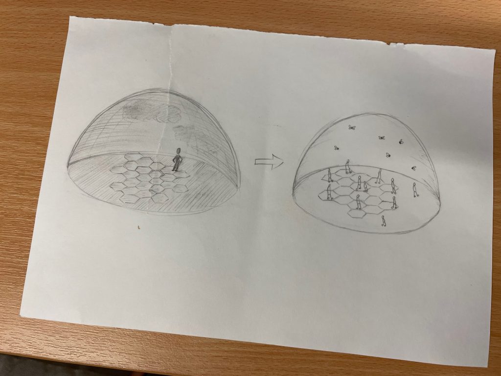
To link this back to bee’s we felt we could create an interactive ‘puzzle’ of some sort, made out of honeycomb pieces which fit together to make a ‘functioning hive’ that could impact the surrounding visuals in the Dome to create a pleasant and enjoyable environment. If the pieces were deconstructed, then the environment would deteriorate, just like the real world without bees.
Week 5
1. Visuals
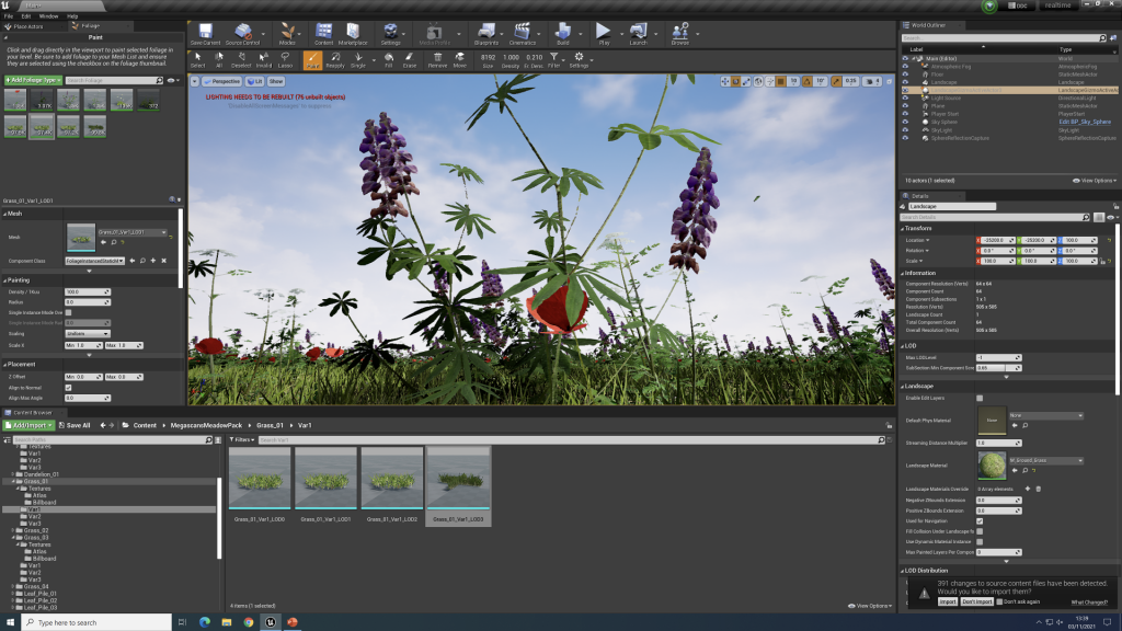
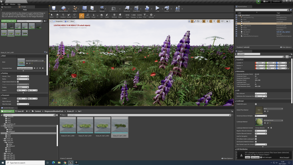
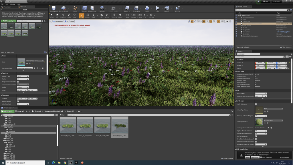
We started thinking about visuals for our installation. We contemplated using Unreal Engine to create an environment that would be projected onto the dome, despite deciding to use threeJS, we did have a go at creating some visuals.
Natasha and I created this meadow in Unreal Engine using some free packs we added to our project. We liked how real it looked and we could get some good angles that represent how the meadow would look to a bee. However we felt this was a bit too complex to use in the dome. There was a lot going on, it would have been very obvious if this environment was distorted. Which in turn could have caused some discomfort amongst the audience. So decided against using the Unreal Engine to create the environment.
Week 6
1. Design
When it came to the design of our installation, we wanted to keep the bee theme very clear as we need our message to be easy to understand.
We decided to keep the visuals abstract based on our skills in threeJS and the challenge of creating convincing realism. We also felt as though the abstract visuals were more appropriate for the experience as the project is not supposed to be a literal representation of a bee hive, it’s open for interpretation.
We also developed the practically of the puzzle concept and after discussion with Rafel we concluded that we wanted the users looking around at the dome, not looking down at a table of honeycomb blocks, so we decided to have the honeycombs on the floor for the audience to stand on, not only does this allow them to look around and enjoy the dome, but also involves the audience a lot more, they get to experience more of the ‘bees eye view’.
2. Concept design
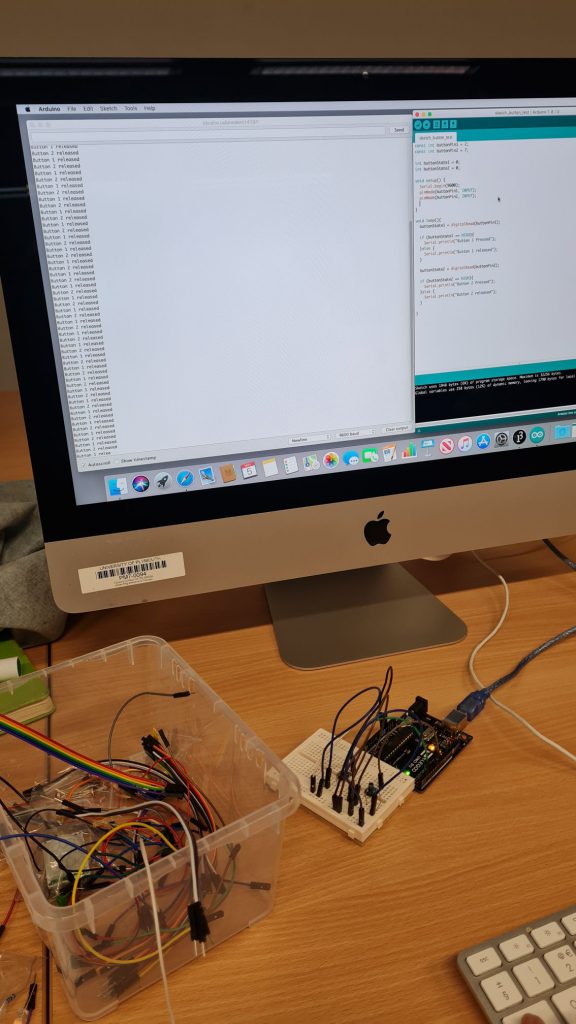
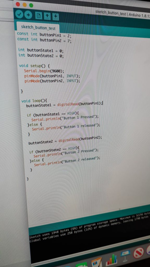
We began to test out getting an input via a pushed button to respond with an ‘on’ value using an Arduino as this is the basis of what we would use to create the code for the pressure sensors.
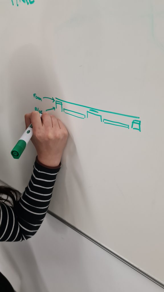
We also began to think about how the pressure sensor would fit under the wooden plate and if we needed to create a compressible support in order to apply weight to the sensor if someone stepped on it.
We submitted the proposal for our installation, which outlined the experience we aimed to create and how we would achieve this.

3. Visiting the Box
During this project, I was able to visit the box in Plymouth. This was a great experience and I really enjoyed learning a bit about Plymouth’s history. My favourite part of the exhibitions I saw was the projection about the history of the Plymouth Sound. Not only was it incredibly informative, I loved the way the information was displayed. A huge projection onto a textured screen really brought the visuals to life. The graphics have been carefully designed to perfectly line up with the environment, giving off an almost virtual reality experience without having to wear a headset. I felt completely immersed and captivated by the experience and definitely set an expectation in my mind for what we could create and how powerful installations like this one can be.
Week 7
1. Sensor Testing
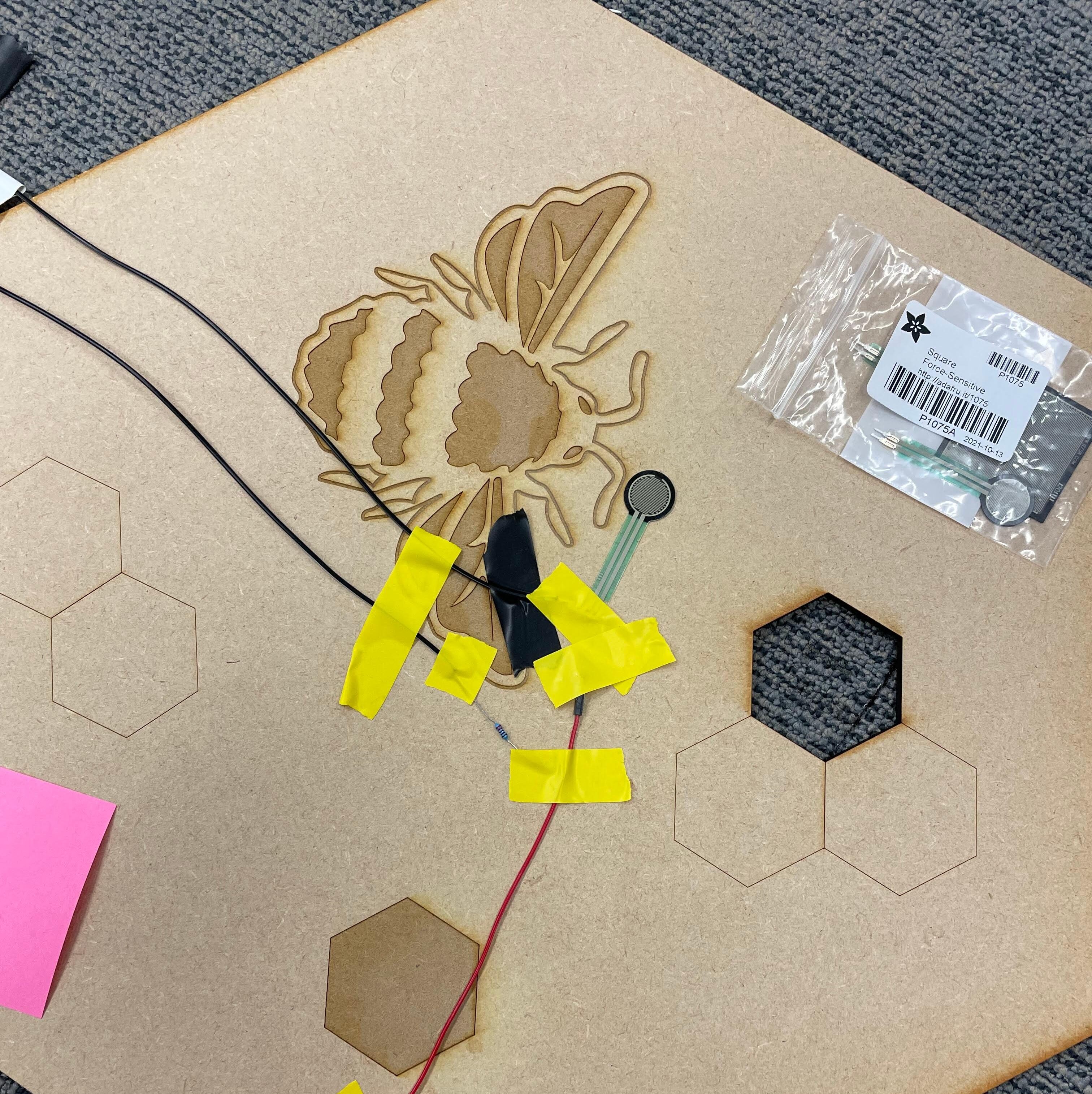
We decided to order 2 sensors to begin testing with. One smaller, less sensitive one and a larger more sensitive one. Natasha and I set up the Arduino to cater for both sensors and used a chopping board to represent our pressure pads, which we would later cut out of wood on the laser cutter.
The tests were very successful as we found that the smaller sensor worked perfectly under the chopping board. While the board was just resting above the sensor, it’s value was zero, but when someone stood on the chopping board, over any part of it, the sensor would significantly increase in value allowing us to determine a threshold to return a ‘on’ or ‘off’ value, depending if the sensor was being stepped on or not. The larger sensor seemed to be too sensitive as it was activated while the board was on it, leaving it more difficult to pinpoint the right threshold to use as it kept varying its value so much, even when untouched. This made the choice to use the smaller sensors very easy going forward.
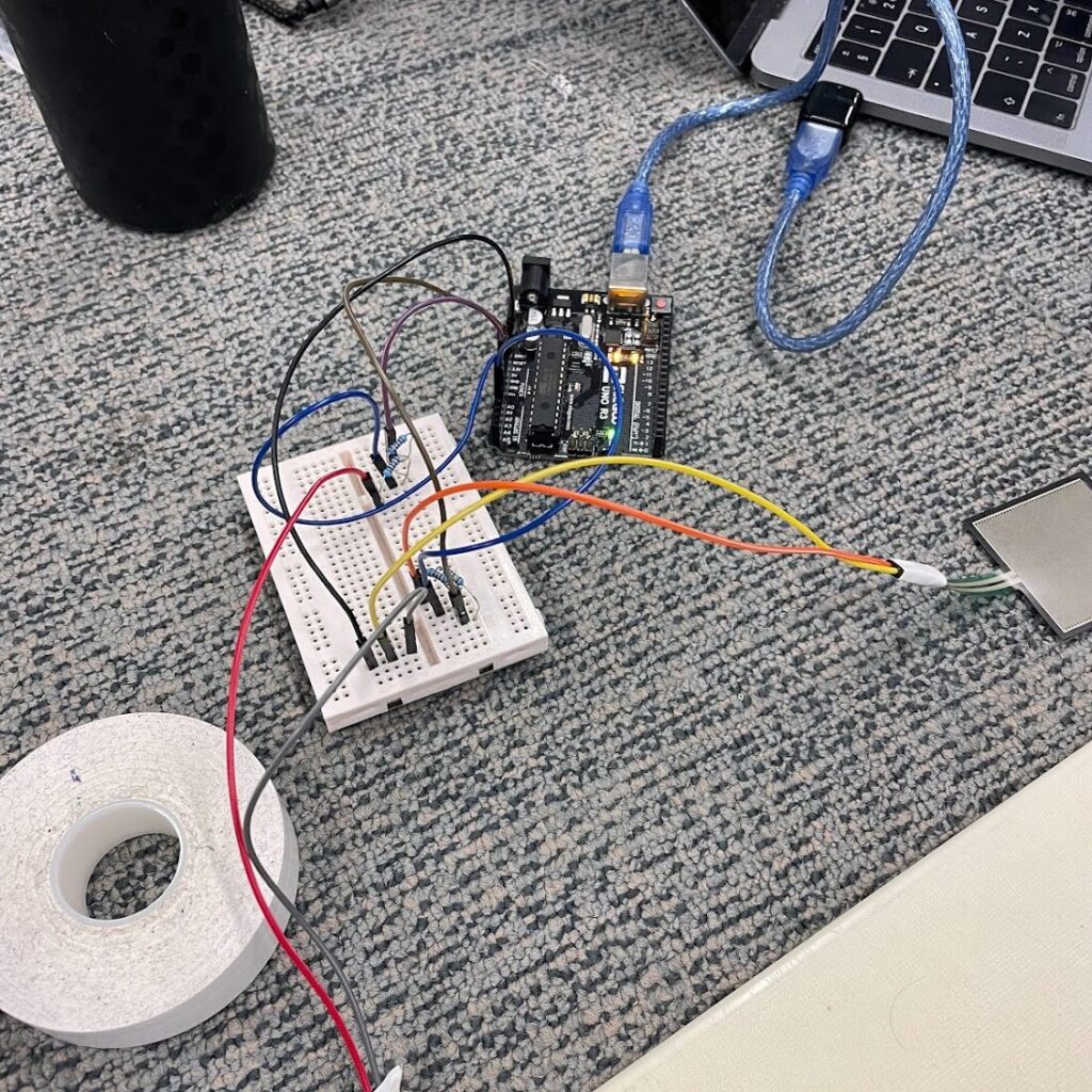
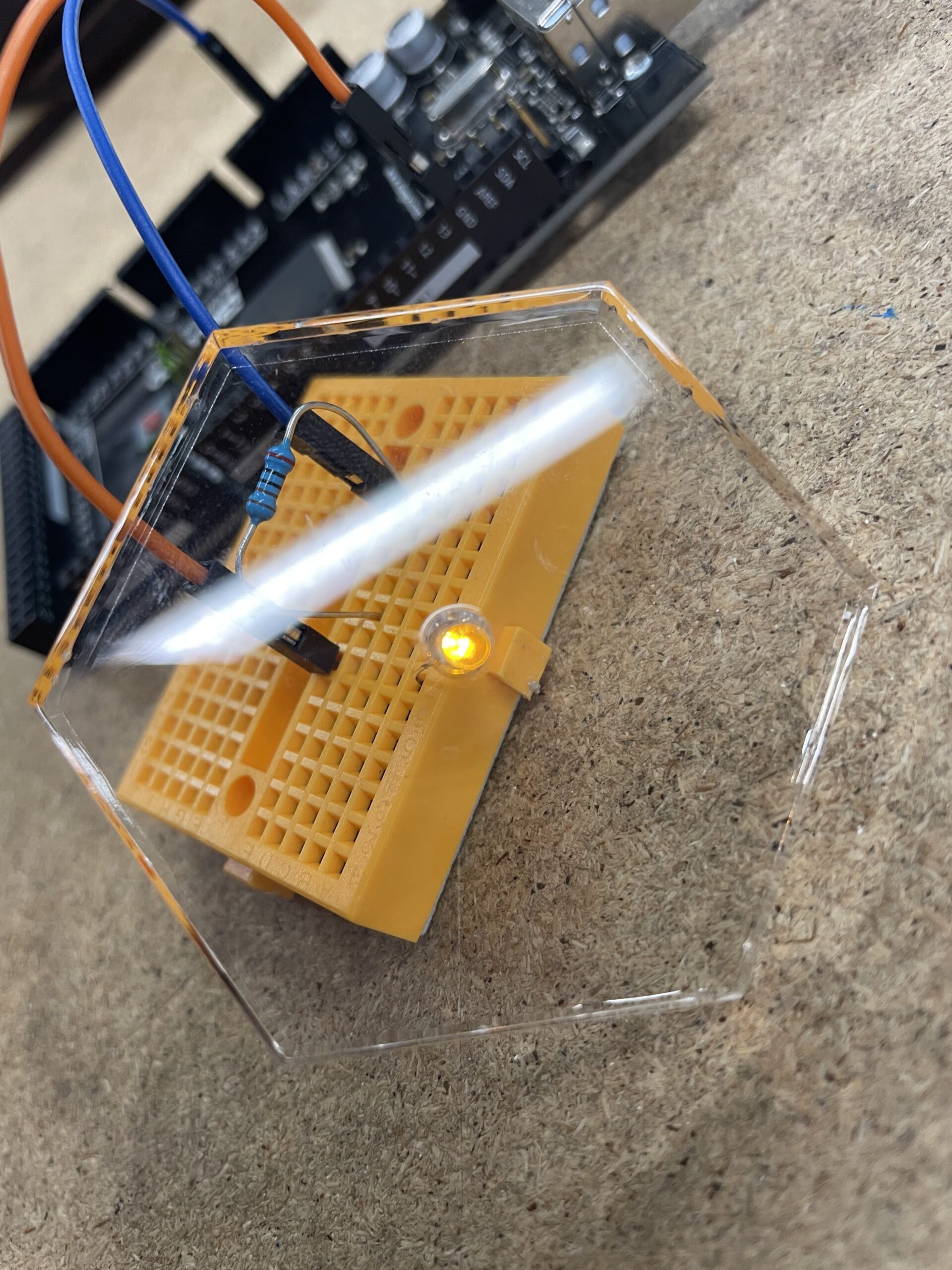
To check the sensors where working, we also included a LED for each sensor into the circuit and created a simple ‘if statement in our code’ to link each LED with a sensor, so if sensor 1 was active, LED 1 would switch on, and the same with sensor 2 and LED 2.
This was really helpful to be able to see how effectively the sensors recognised when they were being stepped on, it also gave us the idea to include LEDs into the final pressure plates as it signals to the user they have activated the sensor.
2. group work
At this point in our project, our group had split off into sub groups. Natasha and I were focused on the physical elements of the project, such as designing and laser cutting out the pressure plates, organising and testing sensors, and creating the circuit. Arthur and Ryan both worked on the technological elements of the project, sorting out the Arduino, sensor readings and creating the visuals. This did mean we were a bit disjointed as a group as for a while we had little overlap. I did worry that when the project did come together we would have trouble merging the two elements. To prevent this we made sure to do regular testing sessions, kept in communication while going through the development process and kept everyone up to date on progress.

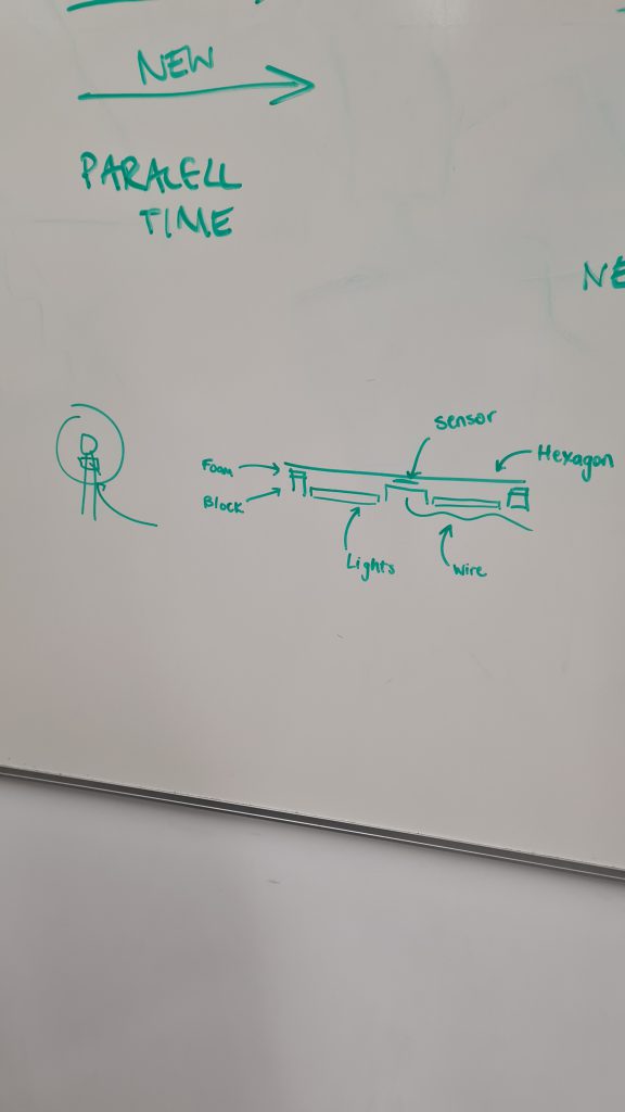
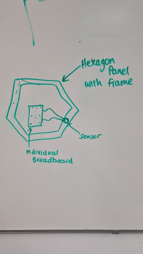
Concept sketches I did of the installation
Week 8
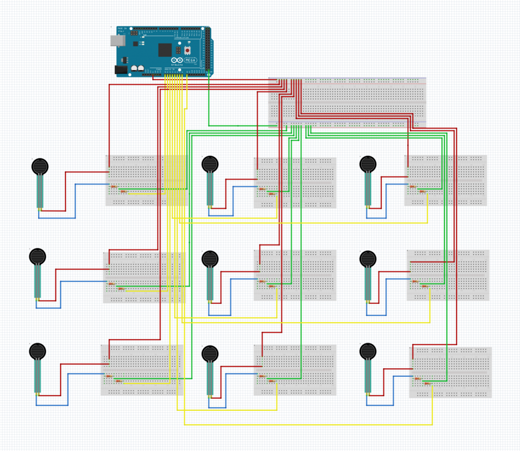
2. Arduino layout
I used Fritzing, which is a program designed to help users layout their Arduino circuits. This was very helpful in allowing me to understand all the connections we would require when building our final circuit. We also discovered we needed to use an Arduino Mega rather than the Arduino Uno that we were currently using as we needed 9 analogue ports and the Uno only has 5.
Week 9
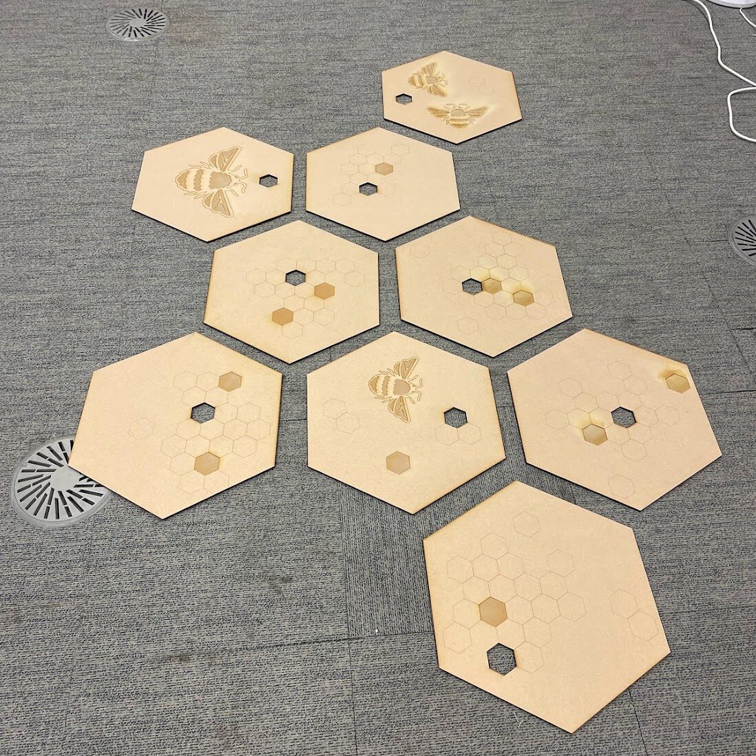
1. Laser cutting pressure Plates
To create the pressure plates for the installation we used 6mm MDF boards which would take the weight of a person and also be thick enough for our LEDs to poke through without the threat of them being squashed.
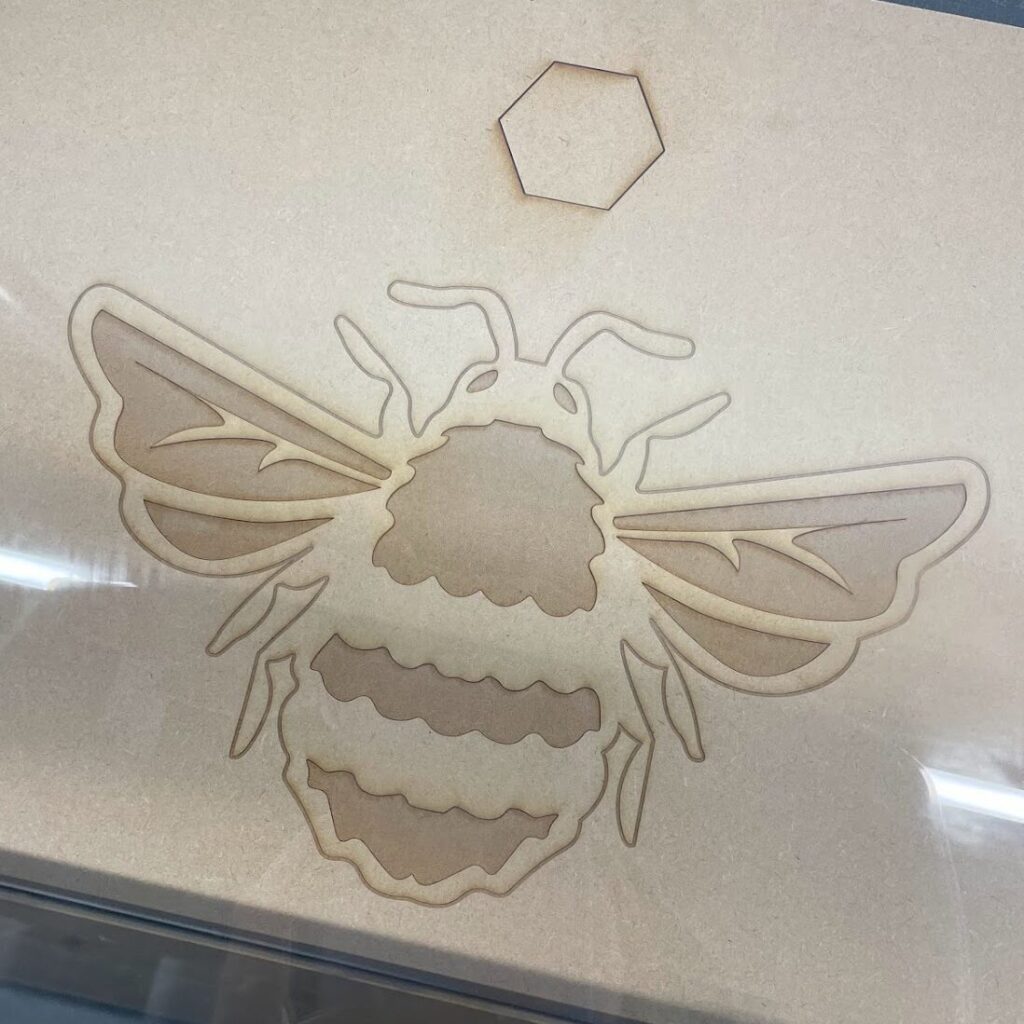
We created the designs for the pressure plates on Illustrator. We wanted them to be interesting to look at, and fit it with the rest of the installation, so we created a honeycomb pattern and I traced a bee illustration to decorate the wood. I think this turned out great, the designs really added to the board and tie the physical elements to the visuals.
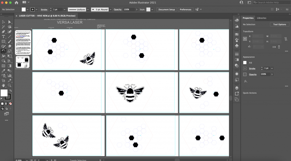
Time Lapse of bee etching
Week 10
1. Creating the Circuit
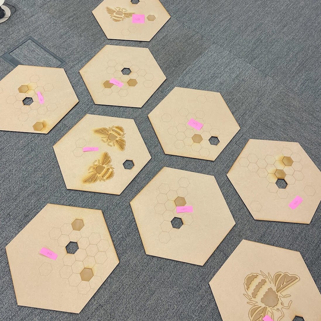
The creation of the circuit was the most challenging part of this project. It required a lot of thought in order to get all the connections right. First we decided to lay out the tiles in the arrangement we wanted. Unfortunately at this point in the project we were having great difficulty accessing the dome. Therefore our backup plan was to project the visuals onto a large, flat screen, which would have a similar effect to the dome. When laying out the tiles we had to consider where the screen would be. We wanted the tile arrangement to look as natural as possible, opposed to a symmetrical shape. We also didn’t want the tiles with bees on them to be too close to each-other as they looked like a centrepiece if they were and it was important to portray each tile was equal with each-other, no one is more important than another. We also had to consider the route the wires would take as we needed 3 wires leading to each tile.
2. Wiring
After discussing our circuit with Stuart, we realised we didn’t need to use breadboards as all the connections can be directly soldered together.
We started the wiring process by laying out all the tiles, and numbering them this meant they were far easier to identify during the creation of the circuit. First we decided to lay the ground wire which needed to reach every tile. We used black tape to mark this out. We wanted the wires to follow the flow of the tiles so we placed them in the channels between the tiles. Next we laid down the power line connected to 5 volts. Just as the ground line this also has to reach from the Arduino to every tile. As both these wires were connected to just one pin, all 9 of our sensors could connect to one wire. So for each we routed out the wire from the Arduino, with plenty of length away from the tiles, to the furthest away tile, then for the rest cut shorter wires to connect to the main one. This process did get complicated as there were over 18 different pieces of wire. However, as we had colour coded and numbered all the pieces of wire this made things a lot easier when it came to soldering as it was clear which wire when where.
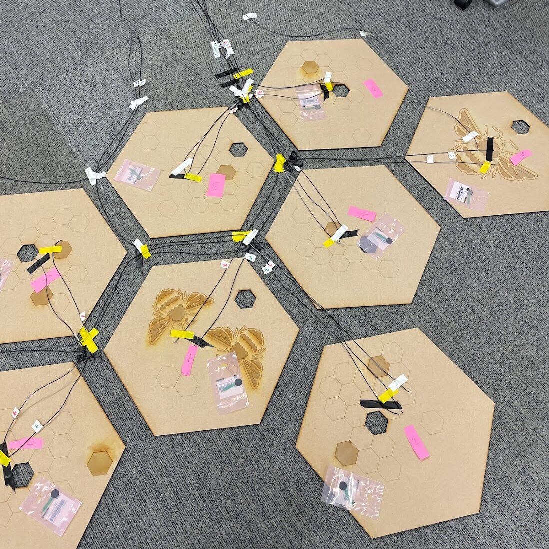
Natasha and I arranging the pressure plates and wires
Next we cut the analogue wires to size. Each of these came out of one side of the sensor and straight into an analogue pin. This therefore required a separate wire per sensor. The analogue wire also acted as a connection to the ground wire using a resistor. We decided to leave the LED wires for later as at this point we had a huge amount of wires and connections to solder.
3. soldering
Next we began the soldering. This was quite a long and tedious process and we had almost 50 connections to make. Fortunately we picked up the skills for it quite quickly and got the majority of the soldering completed in only 2 days.
The most difficult part of the soldering process was connecting the wires to the sensors as the sensor prongs were very close together meaning soldering a wire to one prong and not touching the other was very difficult. It did cause us to break a couple of the sensors due to their fragility. This became an issue as we only had one backup sensor so we had to order another to ensure the installation would be complete.
We finally went on to solder the LEDs which required their own digital pin and the 5 volts power line. We also tidied up the raw ends of all the wires so they were much easier to slot into the Arduino and removed the risk of the raw copper inside the wires touching and disturbing the functionality of the circuit.
Natasha and I soldering all the connections
Week 11
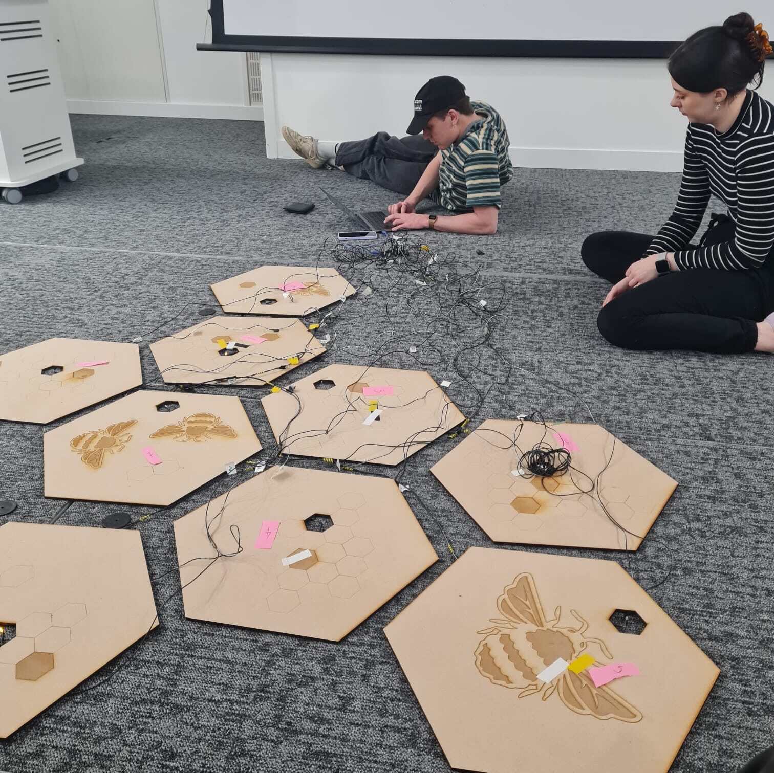
1. Testing
We completed our first full test in the role building. This was our chance to check everything was working before our exhibition. Initially we did run into quite a few problems, the biggest one being that the first 2 analog pins on the Arduino (A0 and A1) had alternative functions which messed with our sensor outputs. In order to fix this we moved all the analogue pins up by 2 places meaning sensor 1 would be plugged into A2.
We also could test sensor 8 as that was the sensor we had broken, however, as all the other sensors and LEDs ended up working perfectly we were feeling confident that it would be an easy fix.
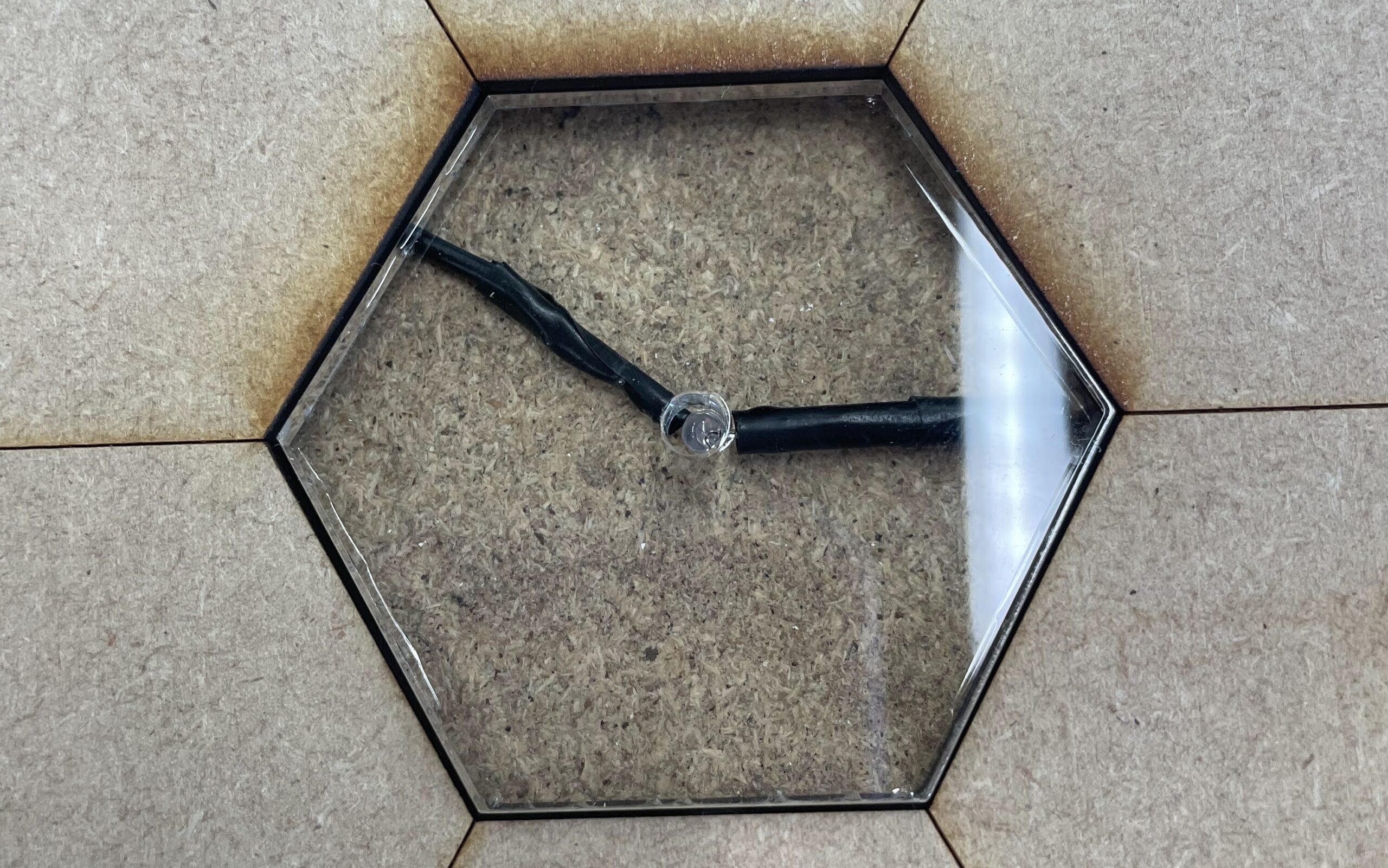
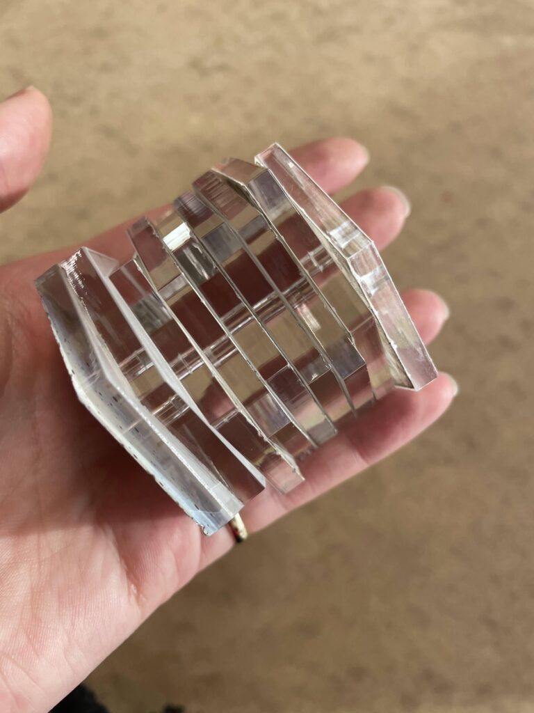
2. Laser Cutting Acrylic
Next we felt like we could enhance the lights a bit on the pressure plates. As we had laser cut a hexagon shape for them to fit in, we decided to cut out some acrylic which I sourced from the Babbage labs. To make the hexagon fit perfectly, I used the shape we had originally drawn when cutting out the wood.
Week 12
1. Video
To finalise our project we had to create a promotional video. We ran an exhibition open to a group of people to collect footage of the installation in action.
Week 13
1. Exhibition
To complete our project we had to set up the exhibition for it to be experienced. Unfortunately this was much more complex than expected. To begin with we already had a broken sensor which we couldn’t replace as we had used up all our spares. We decided to remove this tile entirely as we felt it would be better for the experience to do it with 8 working tiles rather than with a broken one. Next we had to lay out the circuit which was always very challenging due to the amount of wires we have, they get tangled very quickly and in general the connections are pretty fragile. Once we had started to stick down the wires we noticed 2 of the LEDs had broken. Meaning we had to pull it all up again and re-solder them. Once we had fixed that we could begin laying it, however yet again another LED broke.
At this point we really didn’t want to have to start all over again so we decided to twist the LED in without the solder which did consequently work just as well. After finishing off most of the laying, we began testing the sensors and LEDs, this didn’t go very well as which wires go in which pins is complex. Fortunately with a few minutes to spare, Natasha was able to sort all the wires into the correct pins. We got the installation with only one tile not working, we we all considered a massive success as the technology we were dealing with during this project was incredibly temperamental. Despite the extreme pressure of the situation we all worked as efficiently as we could to get it working and this definitely paid off and it was so rewarding to see the project in action. Especially when members of our course stood on every pressure pad. Even though we had all been working on this project for a significant amount of time we had never seen it complete and I was so excited with the result. I think the environment created when all the sensors were active was genuinely beautiful, just as we had set out to create.
Final Thoughts
Realtime was the most adventures and creative module I have ever taken on, we definitely pushed ourselves and created something we are all proud of. The project was incredibly challenging at times, but fortunately, as each of us were so invested, we managed to push through and overcome problems we often didn’t think were solvable. I have thoroughly enjoyed creating something so out of my comfort zone and I am excited to take forward all of the skills I now possess.